Use this setting to achieve the desired hydraulic circuit temperature using two or more boilers connected in cascade.
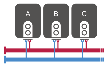
In the example scenario, we will show the configuration for 3 boilers that can be controlled by digital outputs.
Preparation
You should already have the following devices defined:
- Thermostat with return water temperature measurement on the pipe
Digital outputs for each boiler
- Boiler A
- Boiler B
- Boiler C
Virtual analog output
This output will be used as a variable to calculate the total heat output.
Basic configuration
Create a Smart Rule PID temperature controller that will calculate the total output based on the difference between the thermostat setpoint and the current temperature.
| Input device | → Smart Rule → | Output device |
|---|---|---|
| Thermostat | → PID Controller → P = 2, I = 0.2, D = 0 | Total output |
Based on the range of the total output, 3 (or more) boilers will be turned on.
Configuration for the mode where boiler priority is: Boiler A → Boiler B → Boiler C
| Input device | → Smart Rule → Equation | Output device |
|---|---|---|
| <1% | – | – |
| >1% | If the total output > 0.01 Minimum duration: 5 min TRUE: Turn on Boiler A FALSE: Turn off Boiler A | Boiler A |
| >45% | If the total output > 0.45 Minimum duration: 5 min | Boiler B |
| >90% | If the total output > 0.90 Minimum duration: 5 min | Boiler C |
Boiler rotation
To ensure even use of the boilers, additional configuration is required.
Creating a multi-valued switch
Define N+1 states, where N is the number of boilers.
The last state can be defined as Heating inactive, which means the system is not heating.
Name: Boiler Priority
States:
- Priority A (Boiler A → Boiler B → Boiler C)
- Priority B (Boiler B → Boiler C → Boiler A)
- Priority C (Boiler C → Boiler A → Boiler B)
- Heating inactive
Creating a Smart Rule sequencer
This sequencer will rotate priorities as follows:
A → B → C → A → …
| Input device | → Smart Rule → | Output device |
|---|---|---|
| Virtual button to start the sequencer | Sequencer | Boiler priority |
| Step 1: Priority A (duration: 18 hours) | ||
| Step 2: Priority B (duration: 18 hours) | ||
| Step 3: Priority C (duration: 18 hours) | ||
| ✅ Rotate sequence |
Define a separate set of Smart Rule rules restricted to each boiler priority.
See Smart Rules for Priority A in the table below:
| Input device | → Smart Rule → Equation | Output device | Restricting condition |
|---|---|---|---|
| <1% | – | – | – |
| >1% | If the total output > 0.01 TRUE: Turn on Boiler A FALSE: Turn off Boiler A | Boiler A | Type: Multi-valued switch Rule only applies when Boiler Priority is set to Priority A |
| >45% | If the total output > 0.45 TRUE: Turn on Boiler B FALSE: Turn off Boiler B | Boiler B | Type: Multi-valued switch Rule only applies when Boiler Priority is set to Priority A |
| >90% | If the total output > 0.90 TRUE: Turn on Boiler C FALSE: Turn off Boiler C | Boiler C | Type: Multi-valued switch Rule only applies when Boiler Priority is set to Priority A |
A similar set of Smart Rule rules should be applied with a restricting condition for Priority B and Priority C.