The methods of connecting components in different types of buses.
Linear Topology
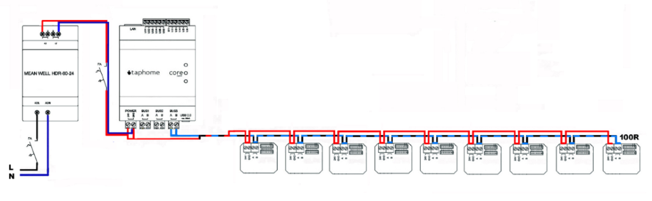
The basic bus configuration consists of a line terminated at the furthest point with a termination resistor, typically 120Ω (for longer runs, 100Ω is acceptable).
Key characteristics:
- Maximum of 32 modules on one bus
- Terminator at the furthest point
- It is not necessary to maintain spacing between modules
Tree Topology
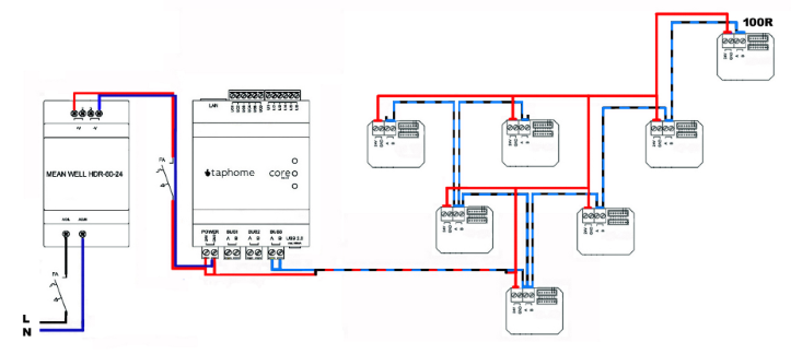
This branched configuration is permissible within the system. The rule for the placement of the terminator remains critical – it must be at the physically furthest point.
Important note: Branching must be done carefully and should be minimized. Excessive branching can cause undefined states in which peripherals disconnect from the bus, leading to system malfunctions.
Star Topology
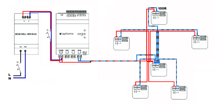
Commonly used in smaller control systems and residential applications with short distances between devices. This topology requires careful attention to cable routing, bundling, and other bus requirements.
Disadvantage: The system may be more prone to communication failures and interference. When using this topology, pay increased attention to the quality of wiring and minimize the length of branches.
Ring Topology 🚫
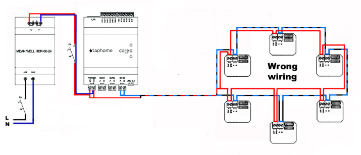
The ring configuration is strictly prohibited for all two-wire communication buses.
Solution for existing ring wiring: If the wiring is already completed in a ring configuration, connect one end to a 120Ω termination resistor instead of the Core output. This will create two parallel lines that maintain functionality in case of cable damage.
Multiple Power Sources
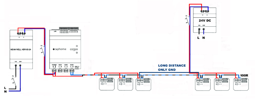
Over extended distances, multiple DC sources can power control modules, provided that their grounds (GND) remain interconnected.
Note: The necessity of this implementation depends on the distances in the project and the choice of cable type.
Wiring Technical Specifications
Recommended Cables
For industrial RS485 and Modbus RTU applications, cables meeting EIA RS-485 standards with a 120Ω impedance are required.
For TapHome control blocks, creating a bus with the following is sufficient:
- Cat5E
- Cat6
- Cat6A and higher
Wiring certified for RS-485 networks is not required.
Twisted Pair
It is very important that wires A and B form a twisted pair. This twisting significantly reduces electromagnetic interference and ensures reliable communication on the bus.
Shielding
Shielded cabling is not strictly required, although it is recommended in environments with higher electromagnetic interference.
Connection of cable shield:
- The cable shield must be connected to GND at the Core module
- At the opposite end, it is not connected anywhere
In case of optically isolated buses on the Bus Extender:
- The shield is connected to GND at the remote source (or the GND of the module located near the source)
- At the ends of the cable, it is not connected
Avoid mixing different types of buses in unshielded multi-pair cables to minimize mutual interference.
Termination Resistor
- Standard value: 120Ω at the furthest point of the bus
- For longer distances: 100Ω is acceptable
- Multiple terminators: Allowed in tree topology if you are unsure of the furthest point.